Long Duration Timer
- Rajkumar Sharma
- 25.144 Views
- moderate
- Tested
- SKU: EL34894
- Quote Now
- 0 Likes


This project is a long duration timer based on 555 timer IC.
Description
This timer project can be used to switch ON/OFF any device after a set time, this circuit can be used in lots of application like switched ON/OFF Radio, TV, Fan, Pump, kitchen timer, the circuit describe here its unique in its own.
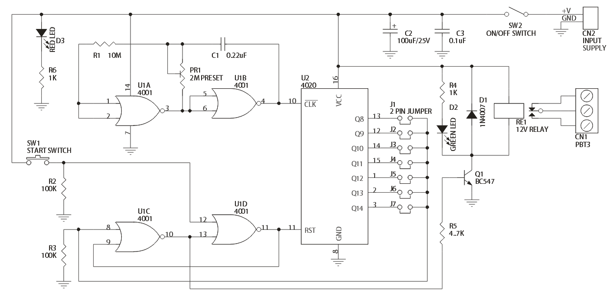
Project has been designed around two CMOS IC CD4001 and CD4020. Two gates of CD4001 make the oscillator and rest has been configured as flip-flop, BC547 transistor is to drive the Relay. Circuit is pretty simple, has jumpers to set the required time duration, Preset is to set the 1Hz oscillator. SW1 is to start the timer, SW2 Power on/off project. Relay output switch contacts can handle 230V AC @ 5Amps
Applications: TV, Audio Equipments, Radio, Fan, Pump, DC Motor, Electronic Projects ON/OFF
Specifications
- Operation Supply: 12V DC Current
- Consumption: 60mA
- D3: Power Indicator
- D2: Timer Operation Indicator
- CN2: Supply Input
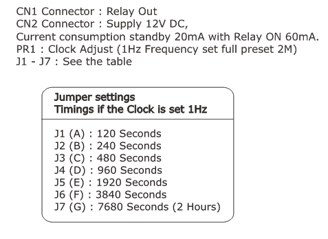
- J1-J7: Time Set (Please see Schematic for Time Duration)
- CN1: Relay Switch Connection Normally Open or Normally Closed
- SW1: Timer Start
- SW2: Timer Supply On/Off
- PR1: 1Hz Frequency Set
Schematic
Jumpers
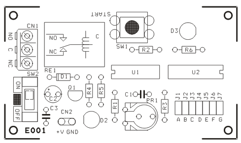
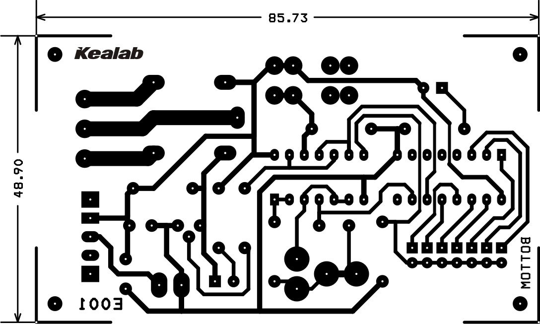
PCB